
I've decided to learn how to build a synthesizer. This is my journey from knowing nothing about anything, to hopefully knowing something about synthesizers.
Happy Fourth of July! It's been a while, but this weekend I made a lot of progress on the synthesizer. Now there's a sawtooth, triangle, square, and sine wave oscillator. There's gliding with a whole host of easing functions. There's an LFO, a hiss/crackle maker, and a Biquad filter. Here's an example with six oscillators going, where it picks random notes and glides between them. Future posts will go into detail about what all of that is, but for now, here's a recording. Up next is porting what I have to a microcontroller.

Long time between updates! Instead of learning about synthesizer software and synthesizer hardware at the same time, I've decided to see if I can write the software part of the synthesizer on my normal computer first. This way I can gain some experience in the audio processing world before trying to scale everything down to run on a microcontroller.
Today I got basic Sine wave oscillators working, along with ADSR envelopes. No midi controls yet unfortunately.
So it turned out that the way I was generating a sine wave was terrible. Instead of picking a pretty standard sampling rate of 8, 16, 24, or 44.1 kHz, I was cranking away as close to 16 MHz as possible. This would have required a super fast chip, and the arduino runs not so super fast.
I rewrote the code to precompute a (variable at compile time) table of sine values for one wavelength. Next, I used the Timer1 library to have a callback called 8000 times per second. An 8kHz sample rate on a 16MHz arduino gives around 2000 clock cycles per audio sample which seems like a reasonable number to me. Unfortunately, increasing the sample rate seems to make things go a little haywire. Even stranger, so does decreasing it. Maybe my math is wrong.
After fighting with lots of bugs of all sorts (is division so much slower on an arduino that I use my entire 2000 cycle quota for a single one?), things seem to roughly work! Here's a video of it playing arpeggios.
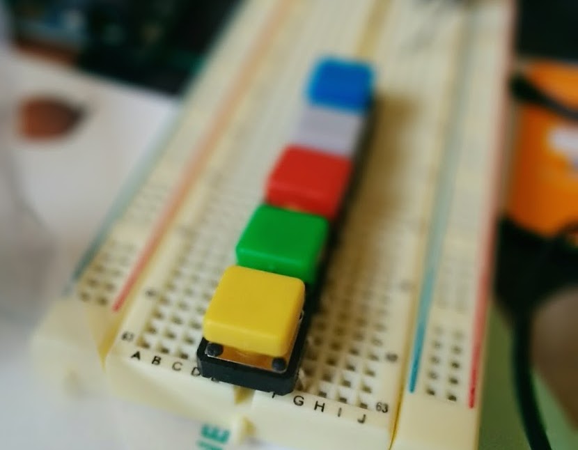
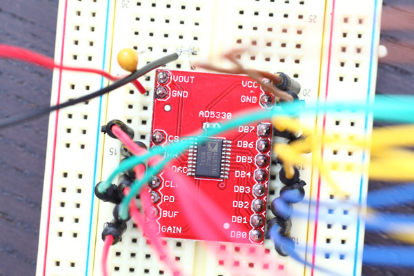
Day one! Soldered together the breakout board for the AD5330. I initially
soldered the pins on crooked and then burned my hand trying to fix them, but
I hear that's what they call learning the hard way.
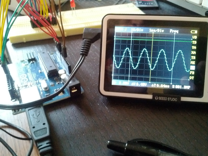
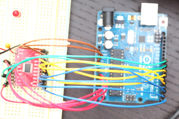
I wired everything up, and got a square wave going! Getting a sine wave
turned out to be much harder but eventually that worked as well, sort of.
//Set up the Arduino Pin locations of the AD5330 Control Pins
#define  CS  18
#define  WR  17
#define  LDAC  16
#define  CLR  15
#define  PD  10
#define  BUF  9
#define  GAIN  14

int delay = 1;
int loopCount = 0;

// Precompute 360 divisions of a sine wave.
char sine360[] = {
  127,129,131,133,135,138,140,142,144,146,149,151,153,155,157,
  159,162,164,166,168,170,172,174,176,178,180,182,184,186,188,
  190,192,194,196,198,199,201,203,205,206,208,210,211,213,215,
  216,218,219,221,222,224,225,227,228,229,231,232,233,234,235,
  236,238,239,240,241,242,243,243,244,245,246,247,247,248,249,
  249,250,250,251,251,252,252,252,253,253,253,253,253,253,253,
  254,253,253,253,253,253,253,253,252,252,252,251,251,250,250,
  249,249,248,247,247,246,245,244,243,243,242,241,240,239,238,
  236,235,234,233,232,231,229,228,227,225,224,222,221,219,218,
  216,215,213,211,210,208,206,205,203,201,199,198,196,194,192,
  190,188,186,184,182,180,178,176,174,172,170,168,166,164,162,
  159,157,155,153,151,149,146,144,142,140,138,135,133,131,129,
  127,124,122,120,118,115,113,111,109,107,104,102,100,
  98,96,94,91,89,87,85,83,81,79,77,75,73,71,69,67,65,
  63,61,59,57,55,54,52,50,48,47,45,43,42,40,38,
  37,35,34,32,31,29,28,26,25,24,22,21,20,19,18,
  17,15,14,13,12,11,10,10,9,8,7,6,6,
  5,4,4,3,3,2,2,1,1,1,0,0,0,0,0,0,0,
  0,0,0,0,0,0,0,0,1,1,1,2,2,3,3,4,4,
  5,6,6,7,8,9,10,10,11,12,13,14,15,
  17,18,19,20,21,22,24,25,26,28,29,31,32,34,35,
  37,38,40,42,43,45,47,48,50,52,54,55,57,59,61,
  63,65,67,69,71,73,75,77,79,81,83,85,87,89,91,94,96,
  98,100,102,104,107,109,111,113,115,118,120,122,124,
};

void setup() {
  for(int pin=0; pin<19; pin++) {
    pinMode(pin, OUTPUT);
  }

  digitalWrite(PD, HIGH);   // Enable the AD5330.
  digitalWrite(GAIN, LOW);  // Set Gain to 1.
  digitalWrite(BUF, HIGH);  // Don't buffer the input.
  digitalWrite(CS, HIGH);   // Set the CS high by default.
  digitalWrite(WR, HIGH);   // Set the WR pin high by default.
  digitalWrite(CLR, HIGH);  // Make sure Clear pin is disabled.
  digitalWrite(LDAC, LOW);

  // Clock in Gain and Buffer Values.
  digitalWrite(CS, LOW);
  delayMicroseconds(10);
  digitalWrite(WR, LOW);
  delayMicroseconds(10);

  digitalWrite(CS, LOW);
  delayMicroseconds(10);
  digitalWrite(WR, LOW);
  delayMicroseconds(10);
}


void loop() {
  digitalWrite(CS, LOW);
  for(int i = 0; i < 360; ++i{
    digitalWrite(WR, LOW);
    PORTD = sine360[i];
    digitalWrite(WR, HIGH);
    delayMicroseconds(delay);
  }
  digitalWrite(CS, HIGH);

  if (++loopCount % 100 == 0) {
   ++delay;
  }
}